
Welcome to part two of our continuing series on building a better business server. Last time we explored the choice of hardware and how we would put the server together. Today we take a look at the step-by-step build process and how things looked when we were finished! We knew we had some challenges ahead of us, but more than anything we were excited to finally put the months of planning into execution, waiting to see our creation live for the first time.
The Processor and Motherboard
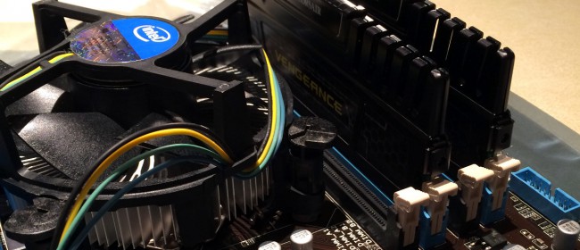
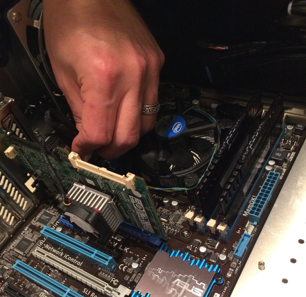
 At the very heart of our server would be our new Intel i7 processor, 16gb of RAM, and the high-quality motherboard which would unite everything together. Being experienced technicians installing these components was not difficult, though we were especially careful with the connectors for the CPU socket as even the slightest bit of dust or grime inside could cause the board to short out and break, taking our expensive processor with it. After setting the Intel heatsink atop the processor we ratcheted it into place, tucked the power cabling out of range of the fan blades, installed the RAM in the BB configuration as recommended by the user guide, and continued on our server journey.
Two RAID Card Problems
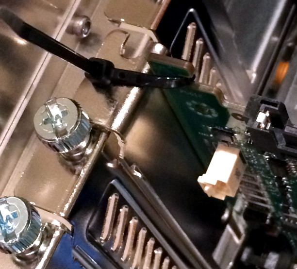
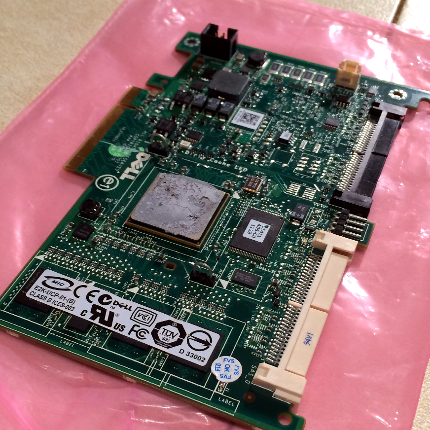 While we were very convinced that the PERC 6/i was the right card for the job, we realized straightaway that there was going to be an issue. The card was designed to rest in a horizontal configuration in a rack-mounted server, and included joining plates for that purpose. We were effectively turning the card 90° and were without a backplate that would hold the daughterboard in. PCI backplates are of a standard size, but the screw holes are unique to each type of card, meaning we had to dig through our inventory for one that would fit well enough that we could screw the pieces together. The closest we could find however was one that just couldn’t provide enough support on its own. Though some very unconventional zip-tie assembly however, we were able to ensure the card would neither droop nor break until a proper backplate could be ordered.
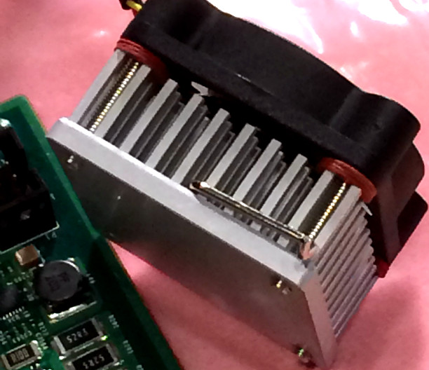 The second problem had to do with cooling. As noted in the previous article the PERC 6/i was known to overheat in desktop systems as there wasn’t enough active cooling on the chipset to keep it operating. To remedy that we had made sure to purchase a custom-order heatsink and fan assembly that would more than handle our server’s needs while it managed our data. Once we fit the fan to the heatsink however we saw that the screws mating the two were too long and would interfere with the card itself. We had to find a way to add space while still maintaining a consistent seal against the chip, else the heatsink would be of no value. With a stroke of genius we realized that non-conductive bolt spacers would not only add height to the screws but also allow us to ensure the tightest fit possible between the fan, heatsink, and chip. With those installed, we used thermal paste and joined the new, more effective cooler and the card.
Installing the Case
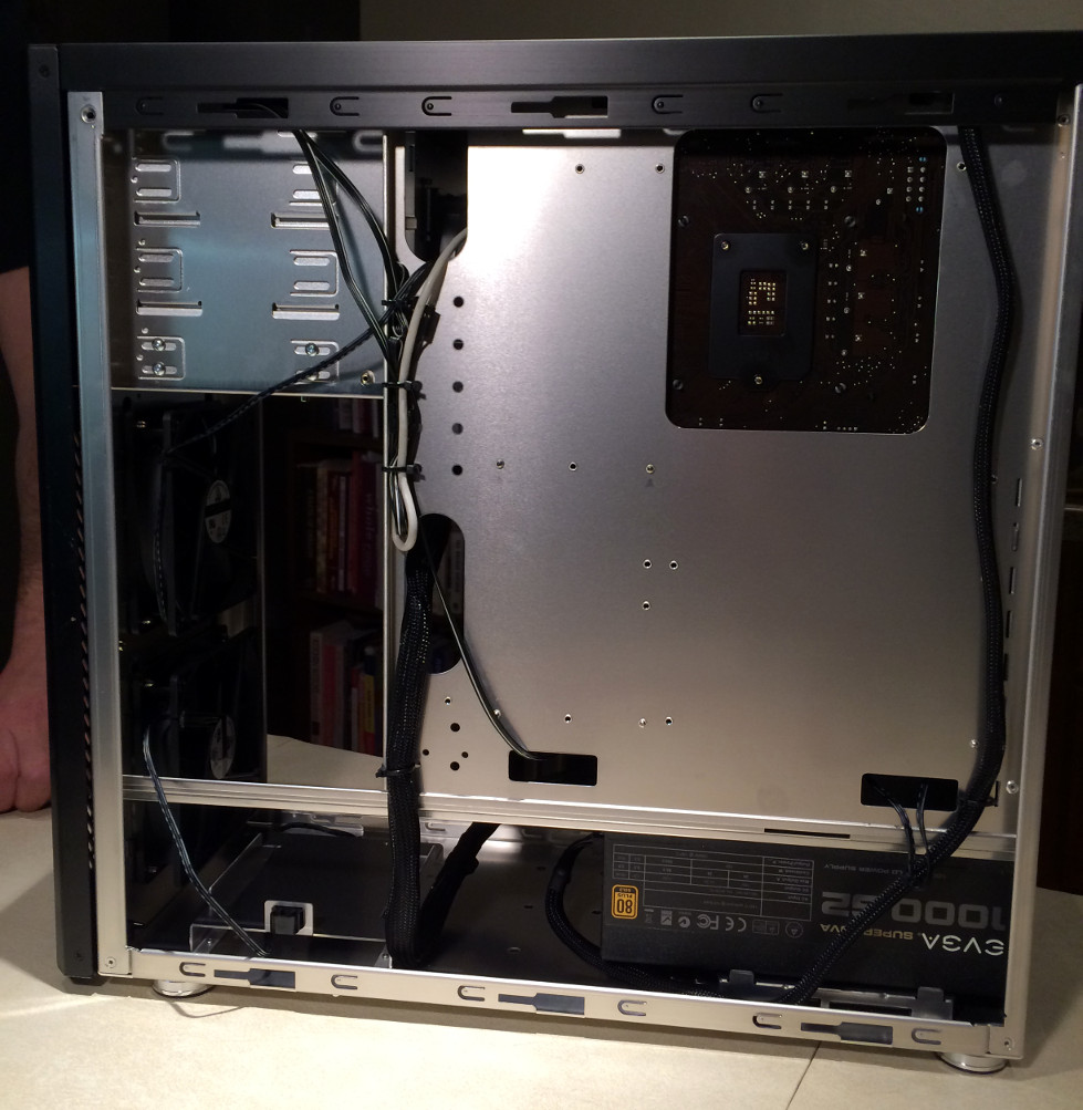
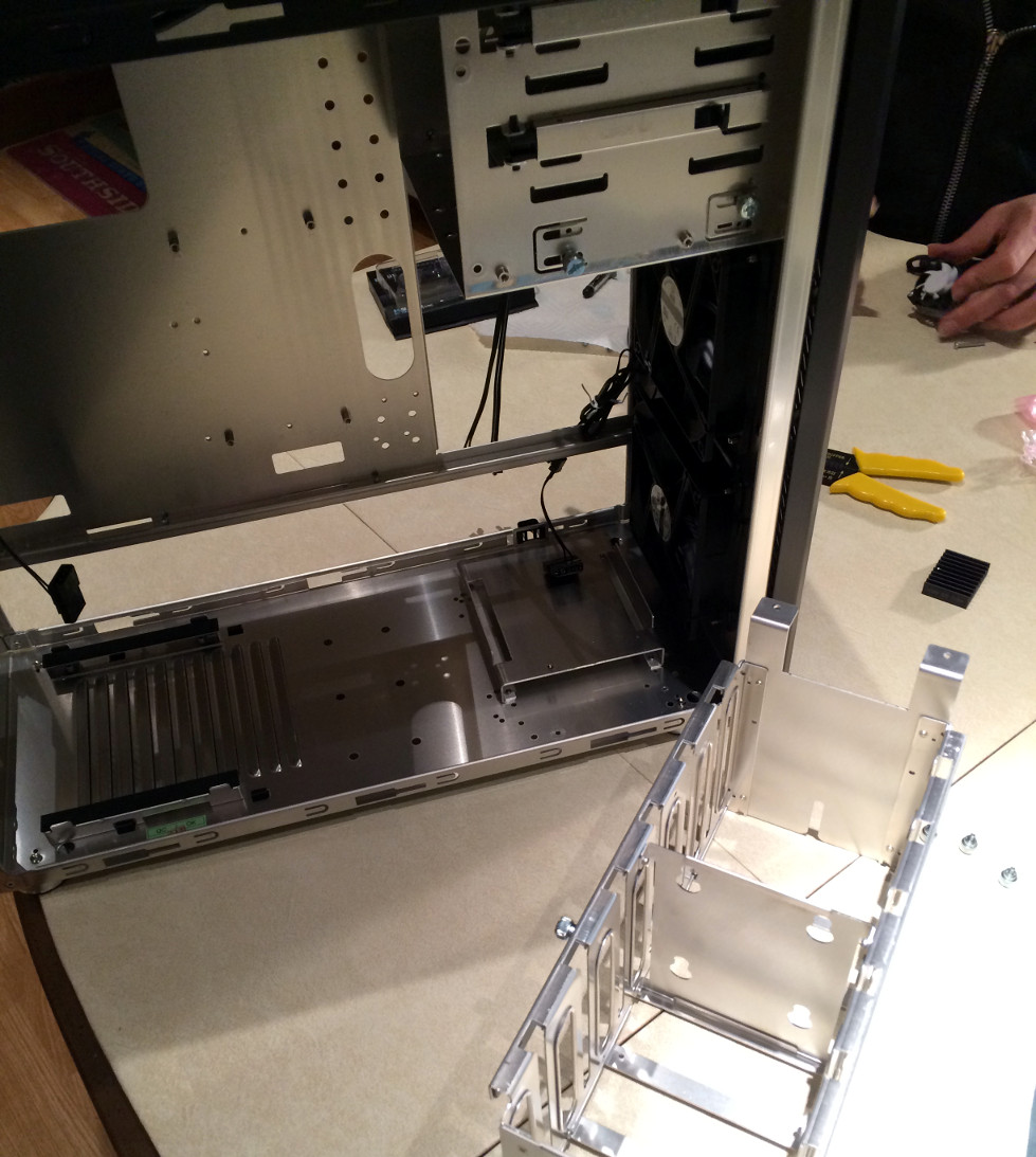 With our biggest hurdles so far behind us we moved on to preparing the case. With a careful eye toward airflow we looked at the cable management options we had available. To increase cooling we removed the internal HDD cage as shown at right and installed the motherboard. Soon we were routing cables and testing our RAID card modifications, which soundly met with our approval.
Harddrives and Hotswap Dock
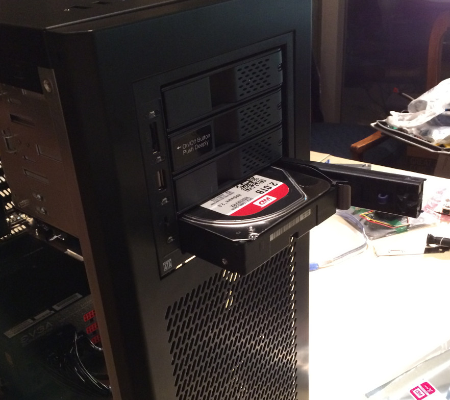
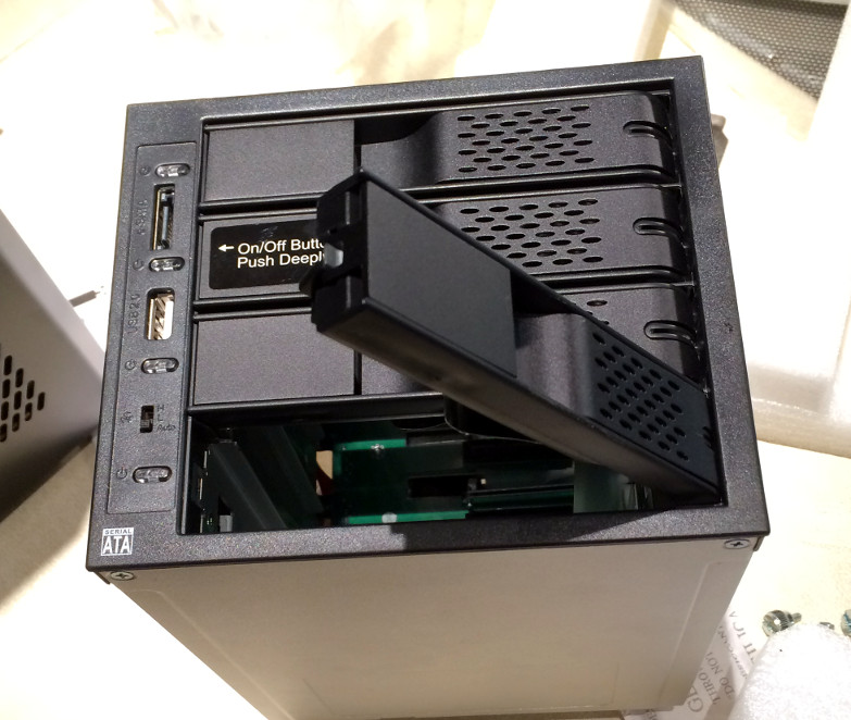 While we had no doubt that we would enjoy the benefits of a dedicated RAID card for some time, we were unsure of third-party tools that would be used to check our drives’ health and to ensure that there weren’t errors. To make identifying and addressing problems as straight forward as possible we installed our drives not inside the case but in an IcyDock hot-swap bay. This device affords us both easy access to the drives in the event of a failure but also per-drive status lights allowing us to verify activity and performance. Combined with the hot-swap capabilities of the PERC 6/i, it was a very sound investment. Unlike many other hot-swap bays, the IcyDock does not require the use of drive carriages, further simplifying future replacements.
Power Supply and Cable Management
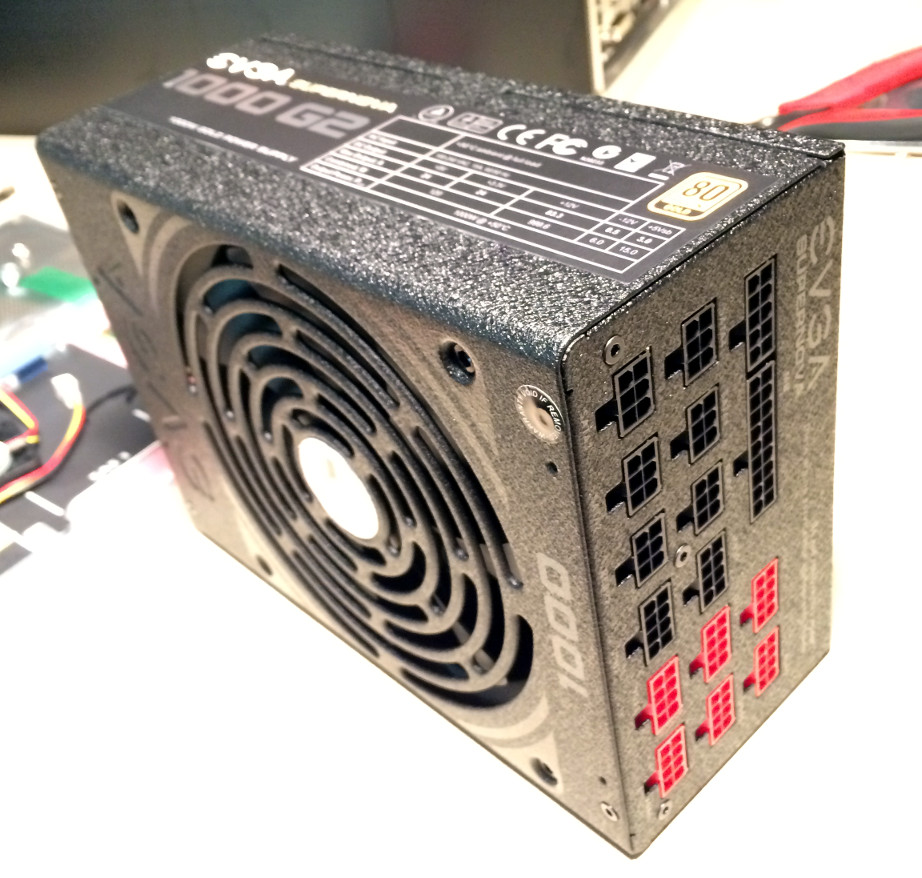 The final piece of hardware to install was the power supply. We wanted to make sure our other components were in place before moving the heavy PSU into place to give us the maximum amount of work space and also to plan our cabling. Loose cables inside a case can interrupt airflow, raising internal temperatures, and even get caught in errant fans, destroying valuable components. In addition to the cables between PSU and motherboard we also had to manage the hotswap dock power, data cables for the harddrive and RAID card, internal fan power, and the motherboard interface controllers for the power and reset switches. Utilizing more zip ties and some creative planning we were able to route cables in the most efficient manner possible, protecting our investment and ensuring that the internal components would be easily accessed for future maintenance if necessary. We were pleased with our foresight to remove the internal harddrive rack, which gave us considerably more options.
Booting it for the First Time
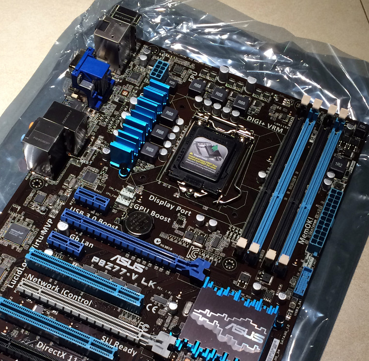
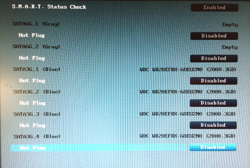
 The biggest test of any new system build is “does it boot?” We connected our power cable, monitor, and keyboard and with great anticipation pressed the power button. Though we have more than thirty years’ experience building computers we both exhaled a sigh of relief as the ASUS logo appeared on screen, soon turning into the BIOS, where we began checking diagnostics such as system temperature, proper voltages, and harddrive recognition.
After making sure everything was connected securely, including our makeshift RAID battery caddy, we celebrated by starting to configure the harddrives for RAID, to be covered in our next installment of our build progress log!


